Leave Your Message

What Are the Top 10 Optical Communication Assembly Types?

Optical Communication Assembly is the quiet infrastructure behind fast, stable data transmission. Inside a data center, thin fiber cables carry signals between switches, servers, and network cabinets. Each connector, splitter, and transceiver affects signal quality, installation time, and long-term maintenance.

Charles K. Kao, widely recognized as the father of fiber-optic communications, said, “The potential of optical fibre is unlimited.” His words still guide modern network design. Yet potential alone does not guarantee performance. Engineers must match each assembly with distance, bandwidth, connector type, environmental conditions, and upgrade plans.

This guide examines the top 10 Optical Communication Assembly types used across telecommunications, cloud computing, enterprise networks, and industrial links. It covers fiber optic patch cords, pigtail assemblies, MPO and MTP systems, active optical cables, transceiver assemblies, PLC splitters, wavelength division multiplexing assemblies, and related connector solutions.

The ranking is practical, not absolute. A compact duplex patch cord may suit a short server connection, while a sealed outdoor assembly may be essential near a cellular tower. Small details matter. A poorly polished end face can create reflection, insertion loss, and frustrating troubleshooting hours.

Some classifications overlap. That is worth admitting. Manufacturers also use different names for similar products. Therefore, the comparison considers structure, application, installation difficulty, scalability, and reliability. It also highlights limitations, because no assembly type fits every network. Readers can then choose with clearer expectations, rather than relying on specifications alone.

What Are the Top 10 Optical Communication Assembly Types?

Defining Optical Communication Assemblies and Ranking Criteria

What Are the Top 10 Optical Communication Assembly Types?

Defining Optical Communication Assemblies and Ranking Criteria

An optical communication assembly combines fiber, connectors, housings, and alignment parts. It carries data between switches, servers, transport equipment, and access networks. The International Telecommunication Union’s Facts and Figures 2024 reports 5.5 billion internet users worldwide. That scale increases pressure on fiber density, insertion loss, and installation accuracy.

The ranking uses five practical measures: signal performance, deployment flexibility, density, reliability, and serviceability. The ten leading types are fiber patch cords, pigtails, MPO trunks, fanout assemblies, transceiver modules, active optical cables, parallel-optic assemblies, wavelength-division multiplexing assemblies, fiber splitters, and hardened outdoor assemblies. Transceiver modules rank highly for compact switching. MPO trunks support fast data-center deployment. Splitters remain vital in passive access networks. However, the boundary is not always clean. A fanout may also be classified as a breakout cable.

ITU-T G.959.1 emphasizes optical interface performance and interoperability. Industry testing reports also show that connector contamination can sharply increase insertion loss, especially during repeated field changes. Tips: Inspect both end faces, control bend radius, and record insertion-loss results before acceptance. Choose assemblies with clear polarity markings. Verify fiber mode and connector geometry against the equipment specification. A dense assembly can save rack space, yet it may complicate repairs. I would not rank density above reliability in harsh environments. That choice deserves reflection.

Fiber Optic Connectors, Adapters, and Patch Cord Assemblies

What Are the Top 10 Optical Communication Assembly Types?

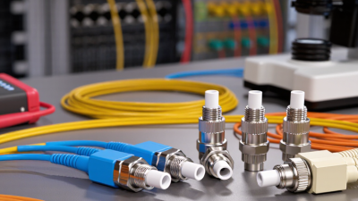
Optical communication assemblies connect transmitters, receivers, panels, and network equipment with controlled optical loss. Ten common types include simplex patch cords, duplex patch cords, single-mode assemblies, multimode assemblies, armored cords, bend-insensitive cords, pigtail assemblies, breakout assemblies, ribbon-fiber assemblies, and loopback assemblies. Connector options often include LC, SC, FC, and ST designs. Each suits different spaces, locking needs, and maintenance habits.

Adapters align two matching or mixed connector interfaces inside a panel or wall outlet. Sleeves must hold ferrules precisely, because slight movement can increase insertion loss. Patch cord assemblies add flexibility between equipment and distribution frames. A short duplex cord may fit a dense rack, while a ruggedized cord better handles repeated movement. Angled-polish connectors can reduce back reflection in sensitive links. However, connector geometry alone does not guarantee performance.

Field experience shows that cleaning and inspection matter as much as component selection. Dust on one end face can disturb an otherwise carefully measured link. Technicians should check polarity, fiber mode, length, jacket rating, and end-face condition before installation. Color coding helps, but it is not foolproof. I have seen correct-looking cords fail after a last-minute routing change. Bend limits are easy to underestimate near trays and hinges. A reliable assembly needs documented test results, compatible adapters, and enough slack for safe service.

What Are the Top 10 Optical Communication Assembly Types? - Fiber Optic Connectors, Adapters, and Patch Cord Assemblies
No. Assembly Type Category Fiber / Interface Typical Configuration Typical Insertion Loss Typical Return Loss Common Applications
1 LC Connector Assembly Small-form-factor connector Single-mode or multimode fiber; 1.25 mm ferrule Simplex or duplex; latch-style housing Usually ≤ 0.30 dB Typically ≥ 50 dB for UPC; ≥ 60 dB for APC High-density data-center panels, switches, transceivers, and telecom distribution frames
2 SC Connector Assembly Push-pull connector Single-mode or multimode fiber; 2.5 mm ferrule Simplex or duplex; keyed push-pull coupling Usually ≤ 0.30 dB Typically ≥ 50 dB for UPC; ≥ 60 dB for APC Fiber distribution frames, passive optical networks, access networks, and legacy premises systems
3 ST Connector Assembly Bayonet connector Primarily multimode; also available for single-mode fiber Simplex; 2.5 mm ferrule with twist-lock coupling Usually ≤ 0.50 dB Typically ≥ 45 dB for UPC-polished versions Industrial networks, building backbone cabling, and older campus LAN installations
4 FC Connector Assembly Threaded connector Mainly single-mode fiber; 2.5 mm ferrule Simplex; threaded metal coupling with keyed alignment Usually ≤ 0.30 dB Typically ≥ 50 dB for UPC; ≥ 60 dB for APC Telecommunications equipment, test instruments, and environments requiring vibration-resistant coupling
5 MPO/MTP-Style Trunk Assembly Multi-fiber connector assembly 8, 12, 16, or 24 fibers; single-mode or multimode Ribbonized or sub-unit trunk cable with multi-fiber push-pull interface Typically ≤ 0.50 dB per mated pair Typically ≥ 20 dB for multimode; higher values available for single-mode designs Parallel optics, high-density data centers, structured cabling, and pre-terminated backbone links
6 LC Duplex Patch Cord Duplex patch cord Two-fiber single-mode or multimode cable LC duplex connector at both ends; common 2.0 mm or 3.0 mm jacket Usually ≤ 0.30 dB per connector Typically ≥ 50 dB for UPC-polished ends Switch-to-panel links, server connectivity, optical transceiver connections, and cross-connects
7 SC APC PON Patch Cord Angled-polish patch cord Single-mode fiber; typically 9/125 µm SC APC connector on one or both ends; often 3.0 mm jacket Usually ≤ 0.30 dB per connector Typically ≥ 60 dB Fiber-to-the-home distribution, optical splitters, subscriber termination points, and access cabinets
8 Fiber Optic Adapter Passive mating sleeve Compatible with matching connector geometry and fiber type Simplex or duplex; sleeve material may be ceramic or alignment polymer Usually ≤ 0.20 dB when properly mated Not normally specified as a standalone value Joining two field connectors inside patch panels, wall outlets, enclosures, and splice trays
9 Fiber Optic Pigtail Assembly Splice termination assembly Single-mode or multimode fiber with one factory-installed connector Usually 0.9 mm buffered fiber; connectorized on one end and spliced on the other Usually ≤ 0.30 dB at the connector Typically ≥ 50 dB for UPC; ≥ 60 dB for APC Fusion-spliced termination in optical distribution frames, closures, cabinets, and splice boxes
10 Breakout Fan-Out Assembly Multi-fiber-to-single-fiber assembly Multi-fiber trunk converted into individually terminated simplex legs Typically 4, 8, 12, or 24 fibers with LC, SC, or other connector options Usually ≤ 0.50 dB per connector Typically ≥ 50 dB for UPC-polished single-fiber ends Connecting high-count trunk cables to individual equipment ports, patch panels, and optical modules

Transceiver, Active Cable, and Receiver Assemblies

Optical communication assemblies support data movement inside data centers, access networks, and long-haul systems. The practical top ten include pluggable transceivers, coherent modules, active optical cables, receiver assemblies, transmitter assemblies, TOSA, ROSA, BOSA, parallel-fiber assemblies, and WDM assemblies. The ranking is not absolute. Application changes the winner. The ITU Facts and Figures 2023 reported 5.4 billion people online, increasing pressure on network capacity and latency. TeleGeography’s 2024 Global Bandwidth Research Service also shows sustained international bandwidth growth. That demand makes assembly selection more important than a simple port count.

Transceiver assemblies remain central because they combine optical conversion, electrical interfaces, monitoring, and thermal control. A 400G module may contain multiple optical lanes, precise alignment, and a small heat path. Active optical cables integrate transceivers with fixed fiber lengths, reducing connector losses and installation errors. They suit short data-center links, especially where copper becomes heavy or power-hungry. Receiver assemblies focus on sensitivity, signal integrity, and stable detection. A weak receiver can erase the value of an excellent transmitter. The ITU notes that submarine fiber systems carry more than 99% of intercontinental data traffic, highlighting the importance of reliable optical endpoints. I would not treat published market rankings as permanent. Power limits, packaging shortages, and evolving 800G designs can change the preferred assembly quickly. Some specifications still look impressive on paper, yet fail under heat, vibration, or repeated mating.

Splitter, Multiplexer, and Wavelength Management Assemblies

Optical communication assemblies form the practical layer between network design and daily service. The ten common types include splitters, multiplexers, demultiplexers, wavelength-selective switches, ROADMs, monitor taps, patch panels, fan-outs, splice trays, and transceiver assemblies. Splitters divide one optical signal across several paths. A 1×32 passive splitter, for example, can serve many access subscribers, but its theoretical splitting loss approaches 15 dB before connector and fiber losses.

Multiplexing assemblies combine wavelengths onto one fiber. Demultiplexers separate them at the receiving end. Modern systems commonly follow the ITU-T G.694.1 wavelength grid, while wavelength management assemblies add filters, taps, and reconfigurable switching. TeleGeography’s 2024 Global Bandwidth Research reported international bandwidth demand growing at roughly 29% annually from 2019 to 2023. That pressure makes compact wavelength control increasingly practical, not merely optional. Small details matter. A dirty connector can erase careful optical engineering.

In field commissioning, engineers normally check insertion loss, return loss, isolation, channel spacing, and power uniformity. OTDR traces can expose a hidden splice fault several kilometers away. Optical power meters verify whether each wavelength reaches its planned budget. LightCounting’s market analyses have also linked rising data-center traffic with sustained demand for higher-speed optical transceivers and related assemblies. Yet dense packaging creates trade-offs. More ports simplify expansion, but they can restrict airflow and complicate maintenance. I would not treat every low-loss specification as equally reliable; test conditions, connector quality, and aging still need independent verification.

Comparing the Ten Types by Application, Performance, and Deployment Needs

What Are the Top 10 Optical Communication Assembly Types?

Comparing the Ten Types by Application, Performance, and Deployment Needs

Optical communication assemblies differ sharply in purpose, reach, and installation effort. Transceiver modules support switch and router links, with speed and fiber compatibility driving selection. Active optical cables simplify short data-center connections, while fiber patch cords offer flexible routing and easy replacement. MPO trunk assemblies reduce cable congestion in dense racks. They also demand careful polarity control.

Pigtail assemblies suit splicing work in cabinets and distribution boxes. PLC splitter assemblies divide one optical signal across multiple users, making them common in access networks.

WDM multiplexer and demultiplexer assemblies combine separate wavelengths over one fiber. Their capacity is attractive, but wavelength planning becomes critical. Optical isolator and circulator assemblies protect sensitive paths from reflected power. Small details matter here.

EDFA assemblies extend transmission reach in long-haul systems, although power balance and noise must be checked carefully. Fiber adapter panels provide organized, repeatable connections during maintenance. They usually deliver less performance improvement, but they reduce handling errors.

In field evaluations, insertion loss, return loss, bend radius, temperature range, and connector cleanliness deserve equal attention. Rankings are never perfect. A low-loss assembly may still fail operationally if technicians cannot access it quickly. Deployment space, testing tools, spare policies, and future bandwidth plans should shape the final choice. Fancy specifications can mislead. A practical design often wins.