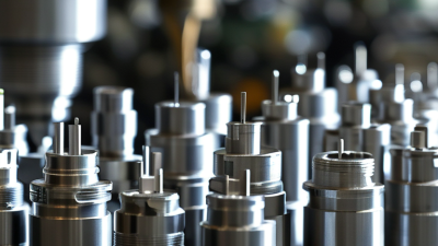
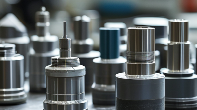
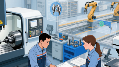
What Are Optical CNC Parts and How Are They Made? This question matters wherever light must travel accurately through a compact mechanical system. Optical CNC Parts are precision-machined components used in lens mounts, mirror holders, sensor housings, apertures, and alignment assemblies. They are commonly produced from aluminum, stainless steel, brass, or engineering plastics. Each material changes the machining strategy.
Industry data shows why this field deserves closer attention. Fortune Business Insights valued the global optical components market at approximately USD 32.16 billion in 2023 and projects continued growth through 2032. Grand View Research also reports strong expansion in the optical coatings market, supported by imaging, healthcare, aerospace, and communications. These reports cover wider optical sectors, not CNC parts alone. That distinction matters. Market figures can sound precise while hiding different product definitions.
Accuracy begins with the drawing. Engineers define tolerances, surface finishes, datum references, and thermal requirements before cutting metal. A CNC mill then removes material through controlled tool paths. Critical bores may require reaming, boring, or diamond turning. Clean handling follows machining, because a tiny chip can damage a lens or disturb alignment. Very small errors matter.
As optical manufacturing expert Dr. John E. Greivenkamp has stated, “Optical design is an art as much as a science.” The same idea applies to manufacturing. Measurement is essential. Coordinate-measuring machines, optical comparators, and interferometric checks help verify the final part. Yet no process is perfect. Tool wear, vibration, temperature, and operator judgment still influence results. Understanding these limits makes Optical CNC Parts easier to evaluate, specify, and improve.
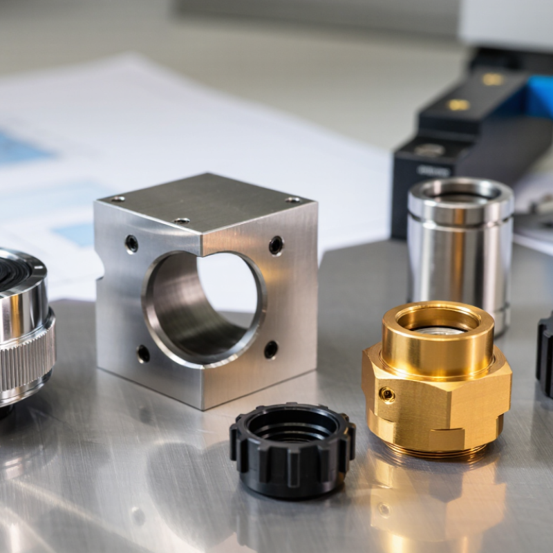
Optical CNC parts are precision-machined components used around lenses, mirrors, sensors, and laser assemblies. Typical examples include lens barrels, mirror mounts, spacers, alignment plates, and detector housings. CNC equipment removes material from aluminum, stainless steel, brass, ceramics, or optical polymers. The part may look ordinary, but a small bore error can shift a light beam by several millimeters over distance.
Their difference lies in control, not appearance. General mechanical parts often tolerate broad dimensional variation. Optical parts may require micron-level positioning, controlled flatness, low burr formation, and carefully specified surface finishes. A 2024 global machine-tool industry report valued worldwide consumption at roughly 86 billion dollars, showing the scale of precision manufacturing. However, optical CNC work represents a much stricter segment. It also demands contamination control. One metal chip inside a lens assembly can scatter light or damage a coating.
Manufacturers commonly use multi-axis machining, probing, fine boring, and final inspection with coordinate-measuring equipment. Technical drawings may reference ISO 10110 practices for optical components and geometric tolerancing standards for mechanical interfaces. Industry quality reports repeatedly emphasize measurement uncertainty, thermal expansion, and process repeatability. In practice, temperature matters: a 100-millimeter aluminum part can change several microns with a modest temperature shift. That detail is easy to underestimate. A polished surface is not automatically an optical surface. Sometimes, the machining strategy needs more review.
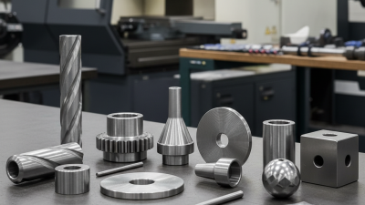
Optical CNC parts combine mechanical accuracy with controlled light behavior. Common materials include aluminum for lightweight housings, stainless steel for rigidity, and titanium for demanding thermal environments. Fused silica and optical glass serve lens or window applications, while ceramics can resist heat and chemical wear. Engineering polymers also appear in low-load spacers and insulating components. Every choice affects alignment, expansion, and surface quality.
SPIE’s 2024 industry report places global photonics sales above one trillion dollars, increasing pressure on manufacturers to improve repeatability. A 2024 MarketsandMarkets analysis also forecasts steady growth in optical coatings through 2029. These trends support tighter CNC designs, including lens cells, mirror mounts, optical barrels, baffles, and adjustable alignment features. Designers often add datum surfaces, threaded retainers, and reference bores for reliable assembly. Small details matter.
Aluminum parts may receive anodizing, while stainless steel often needs careful polishing or passivation. A mirror mount can require low-stress clamping, not just a precise outer diameter. Thermal expansion is easy to underestimate. Fused silica and aluminum expand differently, which can shift focus during temperature changes. Machinists therefore control tool wear, cutting heat, burrs, and inspection temperature. Surface finish alone does not guarantee optical performance. A beautifully machined part can still distort a lens through uneven contact. That mistake remains surprisingly common.
Designing optical CNC parts begins with the light path, not the machine. Engineers define focal length, clear aperture, surface profile, and mounting datums before choosing a cutting strategy. Optical drawings often follow ISO 10110, which specifies surface texture, form tolerances, and coating information.
Small errors matter. A slight edge break can disturb assembly clearance. A rough toolpath can create visible turning marks on a reflective surface. Engineers usually build the part in CAD, then convert critical curves into manufacturable geometry. Grand View Research reported that the global optics and photonics market exceeded USD 800 billion in 2023, increasing demand for repeatable precision components. That scale makes disciplined programming essential.
CAM software then generates toolpaths for roughing, semi-finishing, and final passes. Programmers select tool diameter, spindle speed, feed rate, step-over, and coolant conditions. They also simulate collisions and verify remaining stock before machining. The International Organization for Standardization emphasizes measurement control through geometric product specifications, supporting inspection with calibrated equipment. In practice, technicians compare the finished part with a coordinate measuring machine, profilometer, or interferometric system. The exact method depends on the optical tolerance.
A useful program is not always the shortest one. Fewer passes may reduce cycle time but increase thermal distortion. I have seen overly aggressive settings save minutes and create hours of polishing. Material behavior, tool wear, and fixture stiffness still require judgment. Even a carefully programmed part may need revision after inspection.
Optical CNC parts are precision components such as lenses, mirrors, mounts, and freeform surfaces. Engineers design them in CAD, define optical geometry and tolerances, then use CAM software to generate toolpaths for grinding, diamond turning, or polishing.
The chart shows representative surface roughness targets expressed as Ra in nanometres. Lower values indicate a smoother surface. Actual results depend on the material, tool condition, machine stability, cutting parameters, and measurement method.
CNC machining optical parts begins with a precise engineering model. Designers define the lens seat, mounting surfaces, tolerances, and surface finish. Material choice follows the optical function and working environment. Aluminum suits lightweight housings, while stainless steel supports strength and dimensional stability. Glass and ceramics require specialized cutting methods.
The machine setup controls much of the final quality. Technicians secure the blank, align the workholding, and verify the tool offsets. A probe may check the reference surface before cutting begins. Rough machining removes excess material without stressing the part. Smaller tools then create bores, threads, grooves, and curved profiles. Cutting speed and coolant must match the material. Heat can distort a thin optical housing.
Finishing removes small marks that could affect alignment or light transmission. Diamond tools, fine milling, or polishing may be selected for the specified surface. Cleanliness matters. A single chip can damage a lens seat or change its position. Operators inspect dimensions with coordinate equipment, gauges, and visual checks under controlled lighting. They also examine burrs, scratches, and edge quality. A perfect digital model does not guarantee a perfect part. Tool wear, vibration, and measurement errors still appear in production. Careful records and repeated checks help reveal these weak points before assembly.
Optical CNC parts are precision-machined components used to support, position, protect, or align lenses, mirrors, filters, fibers, detectors, and other optical elements. The table below summarizes common part types, materials, machining steps, and practical quality requirements.
| Step | Process Area | Main Activity | Typical Materials, Equipment, or Values | Optical-Part Considerations |
|---|---|---|---|---|
| 1 | Part Definition | Convert the optical and mechanical requirements into a complete engineering drawing or 3D model. Define interfaces, datum references, mounting features, sealing surfaces, apertures, and inspection requirements. | CAD model, 2D drawing, geometric dimensioning and tolerancing, material specification, surface-finish symbols. | Critical optical axes and datum surfaces should be clearly identified because alignment errors can reduce system performance. |
| 2 | Material Selection | Select a material according to stiffness, mass, thermal behavior, corrosion resistance, machinability, vacuum compatibility, and the operating environment. | Aluminum alloys for low mass and good machinability; stainless steel for strength and corrosion resistance; brass for stable small components; engineering plastics for electrical insulation and low mass. | The coefficient of thermal expansion and material stability are important when the part must maintain optical alignment across temperature changes. |
| 3 | Manufacturing Planning | Select workholding, cutting tools, machining orientation, tool paths, process sequence, and inspection datums before production begins. | Three-axis or five-axis CNC milling, CNC turning, probing, soft jaws, vacuum fixtures, carbide tools, and coolant selected for the material. | The process plan should minimize part movement and preserve the relationship between mounting features, bores, pockets, and optical reference surfaces. |
| 4 | Material Preparation | Inspect incoming stock, cut blanks to a suitable size, remove burrs, and establish stable locating surfaces for the first machining operation. | Bar stock, plate, tubing, or near-net blanks; dimensional inspection; material certificates when required. | Adequate stock allowance is needed for finishing operations, while excessive material removal should be avoided to reduce distortion and residual stress. |
| 5 | Rough Machining | Remove most of the excess material and create the primary external form, internal cavities, bores, mounting pads, and reference features. | High-efficiency milling, drilling, boring, and turning; roughing stock commonly remains on surfaces intended for final finishing. | Balanced material removal helps control warpage, vibration, tool deflection, and heat generation in thin-wall or large-aperture components. |
| 6 | Stress Relief and Stabilization | Allow the workpiece to stabilize or apply a suitable stress-relief treatment when material condition and part geometry make distortion a concern. | Controlled aging or stress-relief procedures may be used for selected metals; the method depends on the material and specification. | This step is especially relevant for thin frames, long bores, precision mounts, and components with asymmetric material removal. |
| 7 | Semi-Finishing | Bring critical features close to final size and prepare accurate datums for the final setup. Re-machine locating surfaces when necessary. | Fine milling, reaming, precision boring, interpolation, and in-process probing. | Accurate datums improve repeatability during the final operation and help control the position of bores, holes, shoulders, and optical mounting surfaces. |
| 8 | Fine Machining | Produce final dimensions, positional relationships, threads, seats, retaining-ring grooves, alignment holes, and other precision features. | Fine milling, precision turning, boring, thread milling, reaming, and controlled cutting parameters. | Common precision targets may range from approximately ±0.01 mm to ±0.05 mm for selected features, but the actual value depends on geometry, material, machine, and drawing requirements. |
| 9 | Surface Finishing | Apply the specified surface treatment to improve corrosion resistance, wear resistance, appearance, cleanability, or light-management performance. | Anodizing for suitable aluminum parts, passivation for stainless steel, electroless plating, chemical conversion coating, polishing, or controlled bead blasting. | Coating thickness, masking, edge buildup, color, outgassing, and internal-surface requirements must be considered because finishes can affect fits and optical stray light. |
| 10 | Deburring and Cleaning | Remove sharp edges, chips, loose particles, machining residue, and contamination from bores, grooves, threads, and optical-element interfaces. | Manual deburring, controlled edge breaking, aqueous or solvent cleaning, filtered air, lint-free wipes, and particle inspection. | Burrs or particles can scratch optical elements, obstruct apertures, interfere with seating, or become contaminants in vacuum and laser systems. |
| 11 | Dimensional Inspection | Verify dimensions, form, position, concentricity, perpendicularity, flatness, surface finish, and thread quality against the approved drawing. | Coordinate-measuring machine, optical comparator, height gauge, bore gauge, thread gauges, profilometer, and calibrated hand tools. | Inspection equipment should be suitable for the tolerance level, and measurements should reference the same datums used during machining. |
| 12 | Alignment and Functional Testing | Confirm that the part interfaces correctly with mating components and that the optical element can be mounted, adjusted, retained, or aligned as intended. | Trial assembly, gauge fixtures, optical alignment tools, rotation checks, aperture checks, and functional fit testing. | Functional testing can reveal issues that dimensional inspection alone may not detect, such as interference, tilt, excessive play, or restricted adjustment travel. |
| 13 | Documentation and Packaging | Record inspection results, material and finishing details, nonconformities, cleaning status, and traceability information before packaging the finished part. | Inspection report, certificate of conformity, revision-controlled drawing, protective film, clean bags, caps, foam, and moisture protection when appropriate. | Packaging should prevent scratches, dust, impact, and corrosion while keeping precision surfaces clean until final assembly. |
Optical CNC parts need more than a clean cut. Their inspection often begins with a coordinate measuring machine, optical comparator, or scanning probe. Technicians check diameter, thickness, concentricity, edge radius, and datum position. ISO 10110 drawing guidance helps define these requirements. ASME B89.7 measurement principles also require uncertainty to remain smaller than the allowed tolerance. A polished surface can still hide a dimensional error. That is easy to miss.
Surface inspection follows machining. Operators measure roughness with a profilometer and inspect scratches under controlled lighting. For optical faces, interferometry can reveal flatness and wavefront errors that ordinary calipers cannot detect.
A 2024 precision manufacturing outlook report estimated that automated inspection could reduce inspection cycle time by 20% to 40% in suitable production lines. The result depends on calibration, fixturing, and operator training. Those details are often underestimated.
Finishing may include deburring, lapping, polishing, ultrasonic cleaning, and protective packaging. Each step can introduce particles or edge damage.
Tips:
Keep the part at a stable temperature before measurement. Record the instrument, calibration status, and uncertainty. Use clean gloves and filtered air. Inspect edges at multiple angles. Do not accept a beautiful surface without checking geometry. A practical review should compare measured results with the drawing, process history, and inspection limits. When results disagree, repeating the measurement is wiser than forcing acceptance.