What Are the Top 10 Types of Height Gauge Measurement Tools?
Choosing among Height Gauge Measurement tools is not a simple matter of selecting the highest resolution. Workshop conditions, workpiece geometry, operator skill, and calibration discipline can change the result. A 0.001 mm display means little when the granite surface is contaminated or the scriber is poorly aligned.
Recent dimensional metrology analyses from MarketsandMarkets and Grand View Research identify automation, portable inspection, and quality-control digitization as major market trends. These reports do not focus only on height gauges. However, they reflect a clear industry direction: manufacturers want faster measurements with traceable data. ISO 14253-1 also emphasizes decision rules when measurement uncertainty affects conformity judgments. That detail matters.
As measurement authority Lord Kelvin stated, “When you can measure what you are speaking about, and express it in numbers, you know something about it.” His principle remains practical on a factory floor. Yet, it is not the whole story. Numbers can look precise while the setup remains unstable.
This guide examines ten common height gauge types, including vernier, dial, digital, electronic, optical, and motorized models. Each tool has a different balance of accuracy, speed, range, and cost. Some suit a quiet inspection room. Others tolerate production pressure better.
Expect useful comparisons, but not perfect answers. The best tool depends on the feature being measured. A narrow slot, a tall shoulder, and a curved edge may demand different approaches. Careful users should question resolution claims, calibration intervals, and real operating conditions before purchasing.
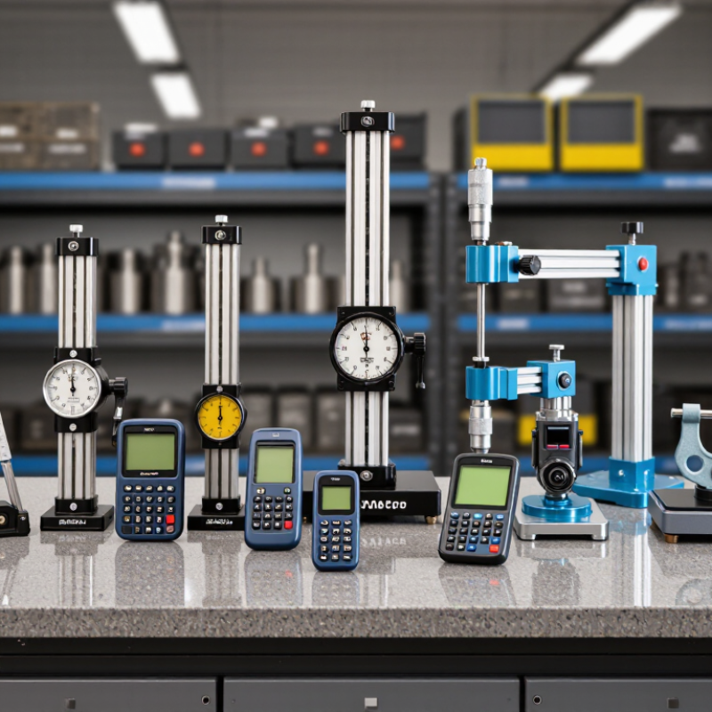
Measurement Fundamentals: Resolution, Accuracy, and Range Under ISO 3650
What Are the Top 10 Types of Height Gauge Measurement Tools?
Height gauges include vernier, dial, digital, electronic, laser, optical, motorized, air, height master, and CMM-based systems. Their usefulness depends less on display technology than on resolution, accuracy, and range. A 0.001 mm resolution does not guarantee 0.001 mm accuracy. That distinction matters.
ISO 3650:2015 classifies gauge blocks into K, 0, 1, and 2 grades. These blocks provide traceable references for setting and checking height gauges. A gauge with a 300 mm range may suit small parts, while a 600 mm model offers greater flexibility but often needs stronger structure. NIST Technical Note 1297 recommends reporting measurement uncertainty with a coverage factor of k=2, commonly representing about 95% coverage under suitable assumptions. The final result should include uncertainty, not only the displayed value. A clean digital number can still be wrong.
Tips:
Clean the surface plate and measuring face first. Control temperature near 20°C when possible. Check probe contact pressure and alignment. Compare readings at several heights, not just zero. Record resolution, calibration status, range, and uncertainty. ISO 3650 is useful here, although it primarily addresses gauge blocks, not every height gauge design. That limitation deserves attention. In practice, operators sometimes trust resolution too quickly, especially when thermal drift or squareness errors remain unexamined.
Classification Criteria: 0.01 mm Versus 0.001 mm Resolution and Repeatability
Height gauge measurement tools vary widely, but resolution and repeatability provide a practical classification. Common types include vernier, dial, digital, electronic, optical, laser, motorized, CNC, scriber, and combination height gauges. Each serves a different inspection environment, from manual layout work to automated production checks.
A 0.01 mm resolution gauge is often suitable for general machining, part marking, and dimensional checks on a surface plate. Its display or scale changes in 0.01 mm steps. However, resolution does not equal accuracy. A worn scriber, dirty base, or tilted workpiece can create larger errors. I have seen operators trust the last digit too quickly. That habit needs correction.
A 0.001 mm resolution gauge supports finer inspection, especially for precision fits, small shoulders, and controlled assembly features. Yet repeatability matters more than impressive digits. Repeatability describes how closely repeated measurements agree under unchanged conditions. Three readings may show 12.347, 12.348, and 12.347 mm. That is useful evidence. A gauge that produces 12.347, 12.352, and 12.344 mm needs investigation. Temperature, vibration, probe force, and surface cleanliness can affect results. Optical and laser types may reduce contact errors, but reflective or dark surfaces can confuse sensors. Digital and electronic models improve reading speed, while vernier and dial types offer direct visual feedback. Motorized and CNC gauges can reduce operator variation, although setup mistakes still remain. Calibration should use traceable standards, and users should record repeated readings instead of accepting one convenient value.
Top 10 Types 1–5: Vernier, Dial, Digital, Electronic, and Column Gauges
Vernier height gauges remain dependable tools for manual layout and inspection work.
Their graduated scales let technicians measure height from a surface plate with careful visual alignment. A carbide scriber can mark a reference line on a workpiece. Dial height gauges add a mechanical indicator for comparing steps, shoulders, and hole locations. The pointer shows small changes clearly, especially during repeated checks. They require steady hands and good eyesight. Reading errors are still possible.
Digital height gauges display measurements on an electronic screen, reducing scale-reading mistakes.
Many models allow zero-setting at the reference surface and quick unit changes. They work well in production areas where operators check several parts in sequence. However, a digital display does not guarantee accuracy. Dust, weak batteries, and poor contact can affect results.
I have learned to verify the zero before every critical measurement.
Electronic height gauges generally use encoders or sensing systems to capture movement with finer resolution.
Some support data output, preset dimensions, and programmable comparisons. These features help quality teams record results consistently. Column gauges use a rigid vertical column and a sliding measuring head, offering stable movement for workshop inspection. Their structure is simple, but alignment still matters. A tilted base can create a convincing yet incorrect reading.
I sometimes rush setup, and that remains a mistake worth correcting.
Clean the surface plate, remove burrs, and confirm the probe touches squarely before trusting any value.
Selection and Calibration: ASME B89.1.6, ISO 17025, and MPE Reporting
What Are the Top 10 Types of Height Gauge Measurement Tools?
Common choices include vernier height gauges, dial height gauges, digital height gauges, electronic height gauges, optical height gauges, laser height gauges, surface gauges, scriber gauges, motorized gauges, and coordinate-based height systems. Each tool suits a different inspection environment. A vernier model offers direct reading and durability. Digital models improve speed, but batteries and resolution can mislead operators. Optical and laser systems reduce contact, although surface finish and alignment still affect results. Selection should consider measuring range, resolution, repeatability, workpiece geometry, and the stated maximum permissible error (MPE).
ASME B89.1.6 provides a useful framework for evaluating height gauge performance and measurement capability. Calibration should verify scale accuracy, squareness, repeatability, and probe or scriber condition. An ISO 17025-accredited laboratory can provide controlled procedures, documented uncertainty, and traceable reference standards. MPE reporting must remain clear. It should identify the instrument, environmental conditions, test points, results, and acceptance decision. Do not report only “passed.” That wording hides useful evidence.
Tips: Clean the surface plate before every check. Confirm temperature stability near 20°C when practical. Record the operator, reference standard, and adjustment history. A zero reading is not proof of accuracy. Recheck after movement, impact, or repair. One practical weakness remains: users sometimes select resolution before understanding uncertainty. That choice deserves review. When the workpiece has burrs, dust, or uneven contact, even a well-calibrated gauge can produce doubtful measurements.
Top 10 Types of Height Gauge Measurement Tools
Representative nominal resolution values are shown in micrometres (µm). Actual measurement capability and maximum permissible error (MPE) depend on the instrument design, measuring range, environmental conditions, and calibration procedure.
For calibration and reporting, the displayed resolution should not be treated as MPE. Verification should follow the applicable requirements of ASME B89.1.6 and a competent calibration system aligned with ISO/IEC 17025, with measurement results, uncertainty, and MPE conformity clearly reported.